This article is about LoRaWAN message types.
LoRaWan messages can be categorized into two types: uplink and downlink messages, depending on their direction of travel.
Uplink messages
Uplink messages are transmitted by end devices and received by the Network Server, often through multiple gateways. In the case where the uplink message is intended for the Application Server or the Join Server, the Network Server forwards it to the appropriate recipient for further processing.
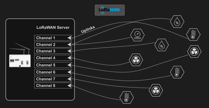
The LoRaWAN server integrated into Wattsense products demonstrates the capability to simultaneously receive data across 8 channels. In theory, we can represent this capability through the following schematic.
 |
Note : Uplinks are randomly distributed among the 8 communication channels of the Lorawan server. |
Downlink messages:
On the other hand, downlink messages are sent by the Network Server to individual end devices. This includes messages initiated by both the Application Server and the Join Server, ensuring targeted communication with specific devices.
Upon receiving a downlink command from the console, the Tower/Bridge (user, PLC, etc.) within the LoRaWAN network will enqueue it into a device-specific queue. The timing of when the downlink command is sent varies depending on the class of the end device:
For Class A devices
The downlink command will be transmitted after the LoRaWAN server receives an uplink message from the sensor. This class follows a scheduled communication model in which downlink messages are transmitted only after an uplink transmission.
Practical case :
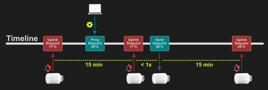
In this practical case, we want to control the temperature setpoint of a thermostatic valve that has a data transmission period of every 15 minutes using an on-site controller.
Here is the schematic diagram to follow for high-quality control :
 |
For Class A devices, if you program 2 downlinks one after the other and if the sensor has not sent an uplink (that would have triggered the first downlink). The latest downlink will overwrite the first one.
|
Here is the resulting diagram :
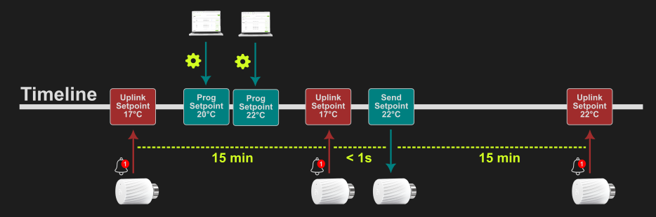
We have noticed that the 20°C temperature setpoint has been overwritten by the 22°C one. You should therefore schedule your setpoints to be sent after a period of more than 15 minutes to avoid downlink deletion.
In the logs, you'll see a "Downlink Lost" message informing you that a downlink has been deleted.
For Class C devices
The downlink command is sent directly by the LoRaWAN server upon receipt of the command. In this class, downlink messages can be sent at any time, even without waiting for an uplink transmission.
Practical case :
In this case, we want to control a single connected thermostat by modifying its temperature setpoint. This thermostat has a transmission period of every 15 minutes.
Here is the basic diagram to understand when controlling a Class C sensor :
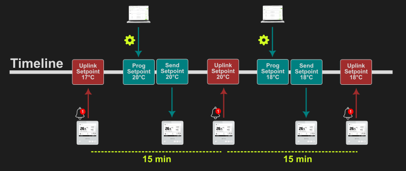
Note that unlike class A, the downlink is sent immediately to the thermostat.
|
It is important to understand that with the Lorawan protocol, you cannot receive uplinks and send downlinks at the same time. This is why, when using Class C sensors and you want to control multiple devices (for example, multiple thermostats), we add a delay between each of the programmed downlinks. This delay is set to 14 seconds. This allows alternating periods between transmission and reception.
|
Here is the principle diagram when you send instructions to several class C sensors (in this example the thermostats) via your PLC :
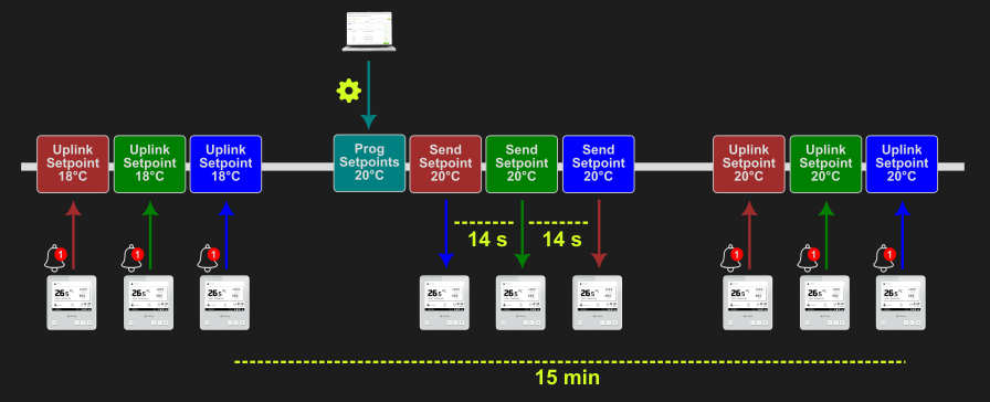
In this case, all the instructions have therefore changed to 20°C and will have taken approximately 14*2s = 28s to be sent.
|
To avoid creating a queue that grows "infinitely," be sure to wait for the scheduled mass mailing to end before sending a new one. Otherwise, the instructions you send could be sent with a "lag" due to sending too frequently.
|
If you need any additional information, please contact us here.